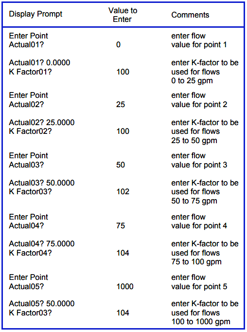
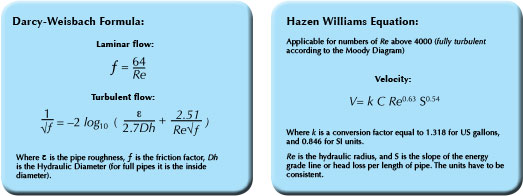
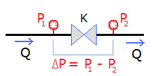
K Factor Flow Formula
Https Encrypted Tbn0 Gstatic Com Images Q Tbn 3aand9gcq8bpidtrauluydqnjndb8xmhxuxxdiy3j1ezvnqzcx5tk3i0hi Usqp Cau
encrypted-tbn0.gstatic.com

Friction Losses In Valves And Fittings For Power Law Fluids
www.scielo.br
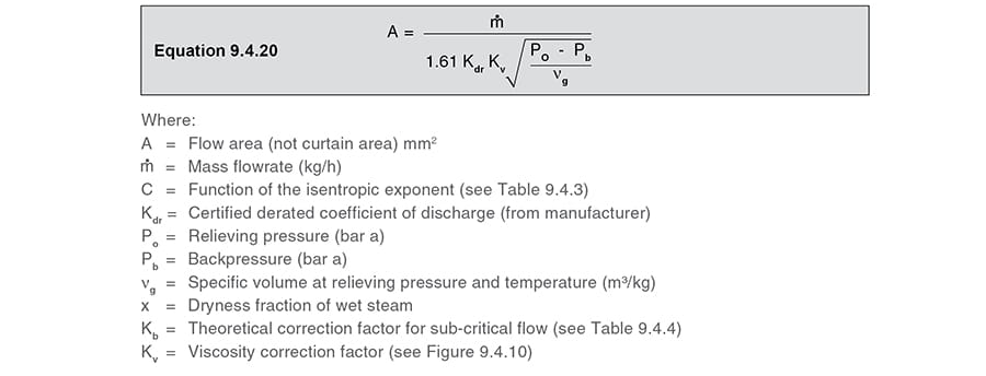
Safety Valve Sizing Spirax Sarco
www.spiraxsarco.com

Automatic Sprinkler System Calculations Pdf Free Download
docplayer.net
Distributor Presentation Mx
www.slideshare.net

Viscosity And Poiseuille Flow Video Khan Academy
www.khanacademy.org
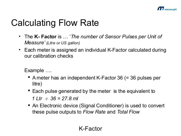
Coriolis flowmeters do not have a fixed k factor number of pulses output per unit of flow.

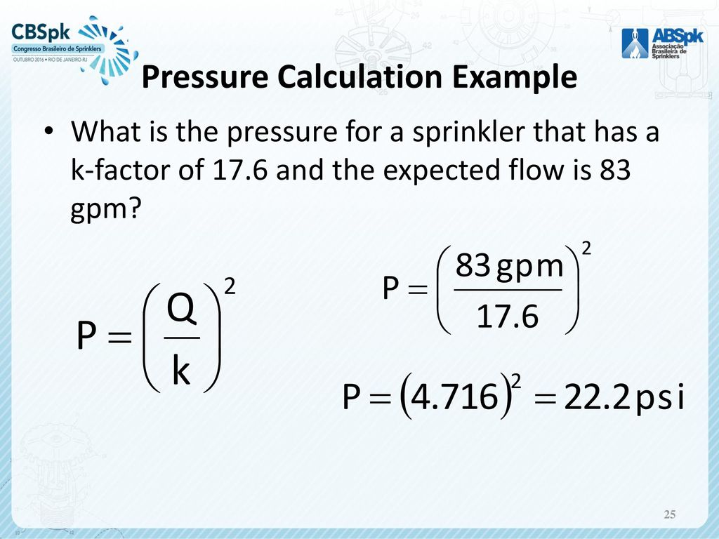
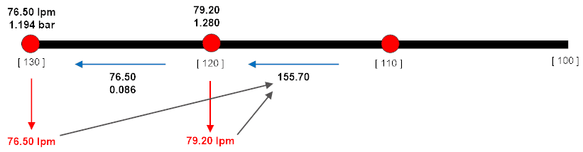
K factor flow formula. Theoretical discharge through circular orifices formula. You can see that the flow has insecure by about 61 lmin each time we changed the k factor by 50 this is because the pressure has remained the same at 150 bar and if you look at the k factor formula above the pressure is squared which will give us 1225 this is then multiplied by the head k factor in this case 50 100 and 150 in are example. Meter k factor is defined as the number of pulses per unit mass or volume at a particular flow rate.
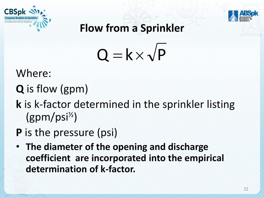
In fire protection engineering the k factor formula is used to calculate the discharge rate from a nozzle. The flow rate of a nozzle is given by where q is the flow rate in litres per minute lm p is the pressure at the. The axial design of turbine flow meter is inherently linear within a known turndown range typically 151 based on velocity of the measured fluid.
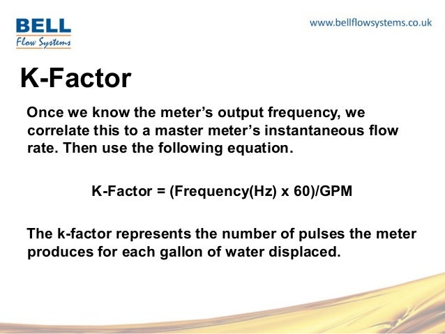
Pulses per barrel from a coriolis meter is instead an adjustable parameter that can be set to any desired value within the range of the meter pulse output channels up to the maximum of the field. The device has unmatched capability of precise and repeatable k factor generation based on the turning of the balanced rotor and the subsequently generated frequency pulse signal via the magnetic coil assembly providing. Every meter in each turbine contains a k factor or a ratio of the pulses per unit of flow.
The number of pulses output per unit of flow eg. Flow meter k factor. Computes a flow rate in gpm given a psi and coefficient of the flow device.
Q p x k q flow rate in gpm p velocity pressure in psi k k factor of flow device. Computes a flow rate in gpm given a psi and a k factor of the flow device. Every time a turbine rotates within a flow rate the turbine blade passes a face of magnet that creates an electronic pulse.
Hydraulics For Fire Protection Ppt Download
slideplayer.com
Compare Flow Of K Factors With New Calculator
www.meyerfire.com
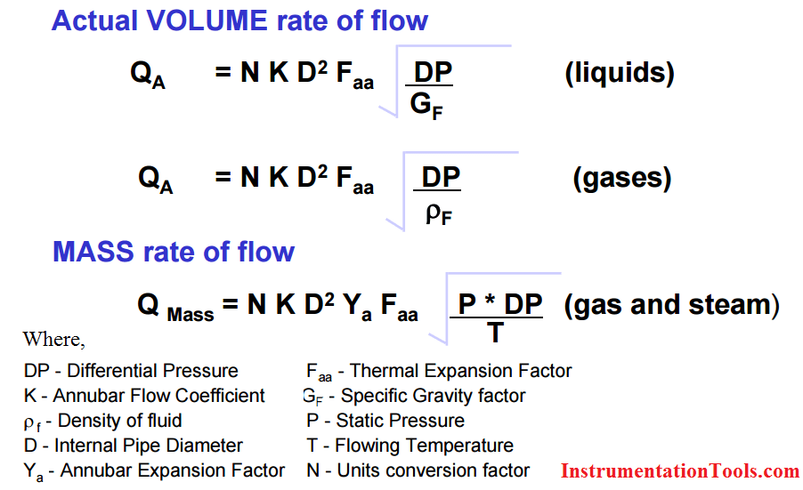
Annubar Flow Meter Working Principle Instrumentationtools
instrumentationtools.com
Pressure Drop
www.svlele.com

Free Hydraulic Calculator Of Fie Sprinkler Hydraulic Calculations
www.canutesoft.com
Air Flow Air Systems Pressure And Fan Performance
www.captiveaire.com
Head Loss Ksb
www.ksb.com

How To Calculate The Flow Rate In Vortex Flow Meter What Is K Factor Can You Give Me An Example Calculation To Understand The Same As Better By
www.wikitechy.com
Autosprink Fire Sprinkler Design Software
autosprink.com
Experiment 4 Energy Loss In Pipes Applied Fluid Mechanics Lab Manual
uta.pressbooks.pub
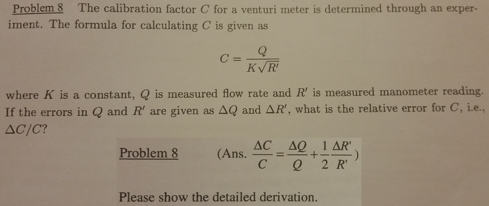
Solved The Calibration Factor C For A Venturi Meter Is De Chegg Com
www.chegg.com

Online K Factor Calculator For Fire Sprinkler Water Mist
www.canutesoft.com

K Factors For Vav Airflow Calculation Download Table
www.researchgate.net
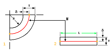
2
Engineering Excel Templates Blog
www.engineeringexceltemplates.com
About Y Factor And K Factor
support.ptc.com

Soil Erodibility In Europe Esdac European Commission
esdac.jrc.ec.europa.eu

Minor Losses In Pipe Flow Wikipedia
en.wikipedia.org

What Is Valve Flow Coefficient Cv Kimray Blog
blog.kimray.com

Basics Of Ultrasonic Flow Meters Factors Affecting Its Performance
instrumentationtools.com

Flow Sensor Wb8nbs
wb8nbs.wordpress.com
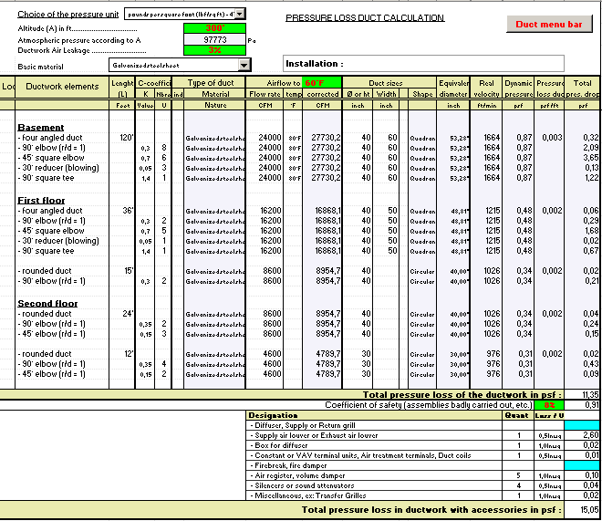
Sizing Duct Ducts Ductwork Air Flow Sizing Friction Loss Pressure Velocity Vav
www.thermexcel.com

Friction Losses In Valves And Fittings For Power Law Fluids
www.scielo.br
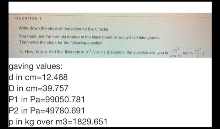
Solved Question 1 Write Down The Steps Of Derivation For Chegg Com
www.chegg.com

Pressure Loss Calculations
www.fekete.com

Free Sprinkler Hydraulic Calculation Software Renewinter
renewinter862.weebly.com
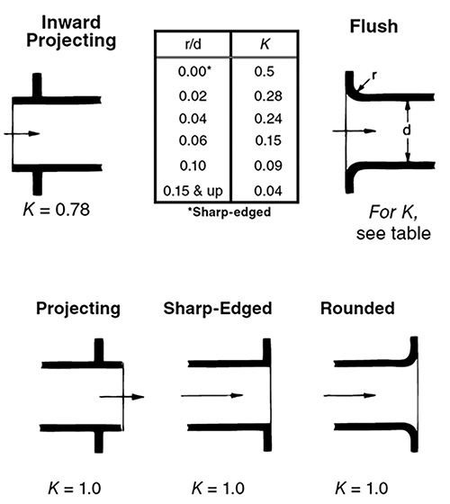
Understand How Valves Fittings Affect Head Loss Pumps Systems
www.pumpsandsystems.com

Valves And Fittings Pressure Drop Coefficient K In Laminar Flow
powderprocess.net

Index Of Wp Content Uploads 2019 04
enggcyclopedia.com
Pressure Loss From Fittings Excess Head K Method Neutrium
neutrium.net

Pdf Mid Year Discounting And Seasonality Factors
www.researchgate.net
Friction Pressure Drop Calculation Campbell Tip Of The Month
www.jmcampbell.com
Discharge Coefficient For Nozzles And Orifices Neutrium
neutrium.net
Http Asgmt Com Wp Content Uploads 2016 02 031 Pdf
Pipe Pressure Drop Calculations Formula Theory And Equations
www.pipeflow.com
Pipe Pressure Drop Calculations Formula Theory And Equations
www.pipeflow.com
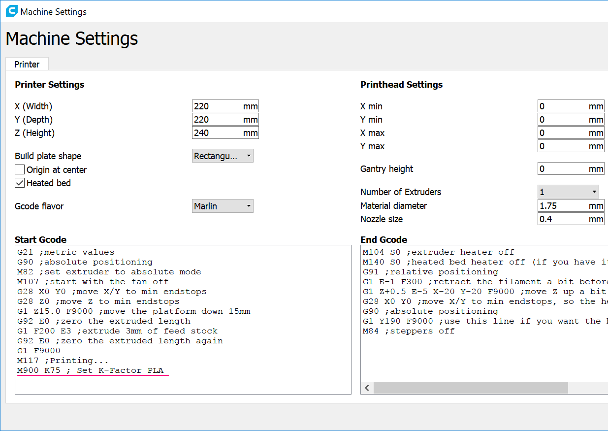
Linear Advance Marlin Firmware
marlinfw.org
Hydraulics For Fire Protection Ppt Download
slideplayer.com

K Factors For Vav Airflow Calculation Download Table
www.researchgate.net

U Values For Dummies Ecomerchant
www.ecomerchant.co.uk
Blancett Turbine Flow Meters
www.slideshare.net
Flow Meter K Factor And Calculations Instrumentationtools
instrumentationtools.com
Domestic Water Piping Design Guide How To Size And Select Domestic Water Piping
www.engproguides.com
Air Flow Air Systems Pressure And Fan Performance
www.captiveaire.com

Valves And Fittings Pressure Drop Coefficient K In Laminar Flow
powderprocess.net

The Importance Of Pressure And Temperature Compensation Of Natural Gas Meters
www.2ea.co.uk
Sizing Duct Ducts Ductwork Air Flow Sizing Friction Loss Pressure Velocity Vav
www.thermexcel.com

Soil Erodibility In Europe Esdac European Commission
esdac.jrc.ec.europa.eu
Http Fluid Itcmp Pwr Wroc Pl Znmp Dydaktyka Fundam Fm Lecture11 12 Pdf

Chapter 5 Introduction To Crop Evapotranspiration Etc
www.fao.org
What Is The K Factor And How Do We Use It In Hvac Applications Hvac Brain Northrich Parts
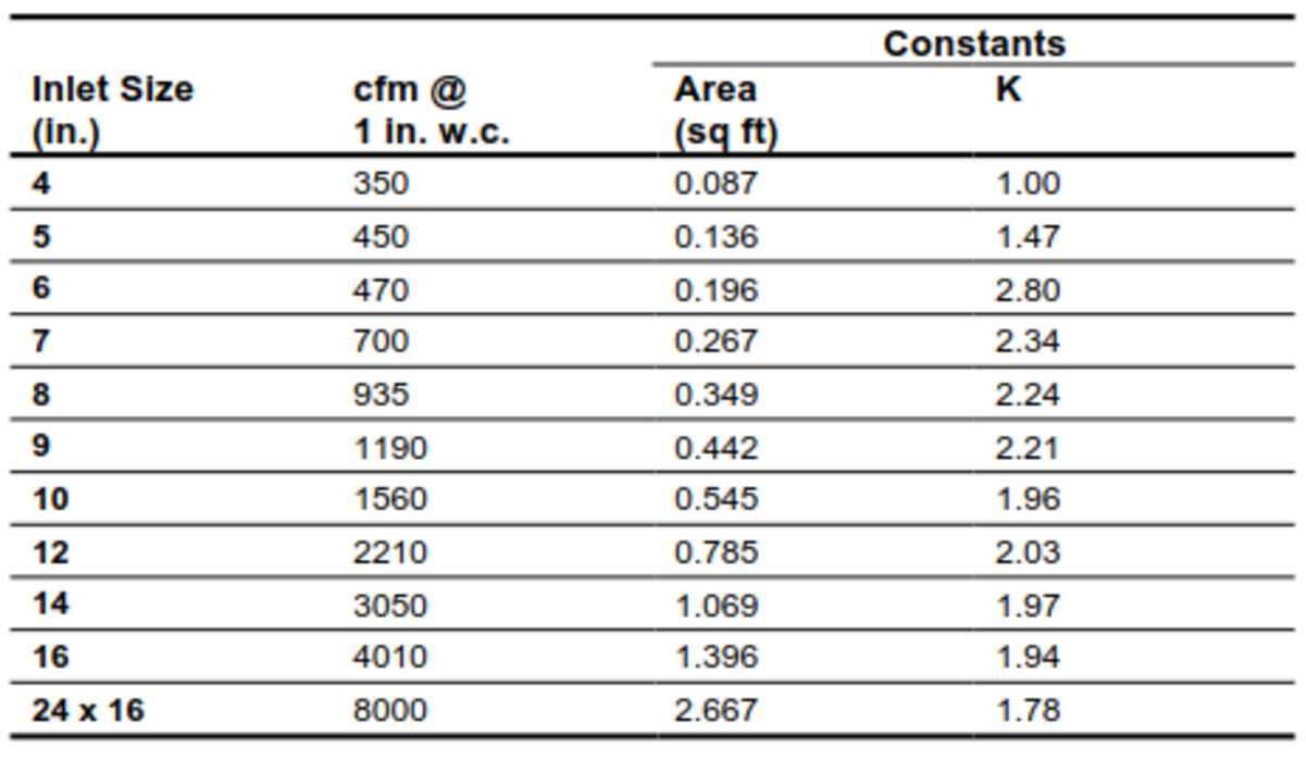
www.hvacbrain.com
2

Hydraulics For Fire Protection Ppt Download
slideplayer.com

Turbine Flow Meter Calibration Procedure Calibration Instrumentation Forum
instrumentationforum.com
Turbine Flowmeters Part 1 Details Of The Basic Axial Turbine Flowmeter Fierceelectronics
www.fierceelectronics.com
Fundamentals Of Hplc 10 The Retention Factor Youtube
www.youtube.com
Chemical Engineering Removal Of Specific Heat Ratio K In The Mach No Critical Pressure Calculation
brojowesi-chemicalengineering.blogspot.com

Reducer K Value Enggcyclopedia
www.enggcyclopedia.com
How To Calculate A Fire Sprinkler System
www.canutesoft.com
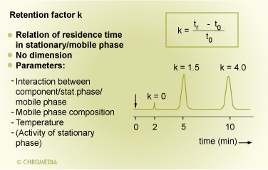
Separation Parameters In Gc Chemistry Libretexts
chem.libretexts.org
1
encrypted-tbn0.gstatic.com

Objectives Template
nptel.ac.in

Calectro Cps D Mb Differential Air Pressure Sensor With Modbus For Ventilation Installations 24v Br Illuminated Display Adjustable K Factor For Volume Flow Calculation Supplied With 2 M Hose And 2 Nipples
www.calectro.com

Objectives Template
nptel.ac.in

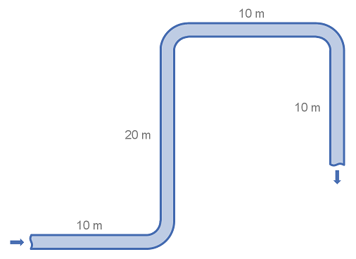
Losses In Pipes
me.queensu.ca
Numerical Analysis Of Friction Factor For A Fully Developed Turbulent Flow Using K E Turbulence Model With Enhanced Wall Treatment Topic Of Research Paper In Mechanical Engineering Download Scholarly Article Pdf And
cyberleninka.org
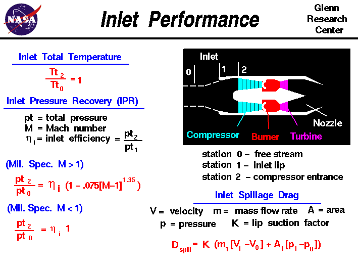
Inlet Performance
www.grc.nasa.gov
Calculating Piping Losses And Their Effect On Pumping Modern Pumping Today
modernpumpingtoday.com
Download Fire Sprinkler Design And Check Tools For Android Fire Sprinkler Design And Check Tools Apk Download Steprimo Com
steprimo.com
Safety Valve Sizing Spirax Sarco
www.spiraxsarco.com
V Notch Weir Discharge Calculator And Equations
www.lmnoeng.com
Orifice Nozzle And Venturi Flow Rate Meters
www.engineeringtoolbox.com
2

P Firefighting Hydraulic Calculation Pdf Fire Sprinkler System Flow Measurement
www.scribd.com
Control Valve Sizing Fluidflow Fluidflow
fluidflowinfo.com
Hydraulic Calculations Of Sprinkler Systems Springerlink
link.springer.com
Magnatrol Formulas
www.magnatrol.com
Linear Advance Marlin Firmware
marlinfw.org

Compare Flow Of K Factors With New Calculator
www.meyerfire.com

Basic Flow Measurement Ppt Video Online Download
slideplayer.com

7k Factor Formula For Fire Sprinklers Fire Sprinkler System Liquids
www.scribd.com

Hydraulic Calculation In Piping Networks What Is Piping All About Piping Engineering
whatispiping.com
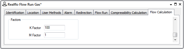
Scadapack Modbus Realflo Driver Guide Aga 7 Factor Properties Configuring A Scadapack Modbus Flow Run
gtg.ddns.net
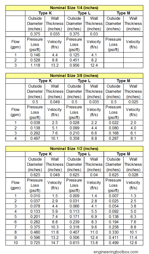
Water Flow In Copper Tubes Pressure Loss Due To Fricton
www.engineeringtoolbox.com

K Factors For Simultaneous Volumetric And Mass Flow Measurement Tutorial Youtube
www.youtube.com
Flow Meter K Factor And Calculations Instrumentationtools
instrumentationtools.com

Hydraulics For Fire Protection Ppt Download
slideplayer.com
Kv Cv Flow Coefficient Valvias
www.valvias.com
Carrier Tech Tips Calculating Cfm Youtube
www.youtube.com

Experimental Study On The Effect Of Injector Nozzle K Factor On The Spray Characteristics In A Constant Volume Chamber Near Nozzle Spray Initiation The Macroscopic And The Droplet Statistics Sciencedirect
www.sciencedirect.com
Https Encrypted Tbn0 Gstatic Com Images Q Tbn 3aand9gctamzuigtgz1i6texlievpzvknjv5tffnwc4wahkjbuke1jergk Usqp Cau
encrypted-tbn0.gstatic.com
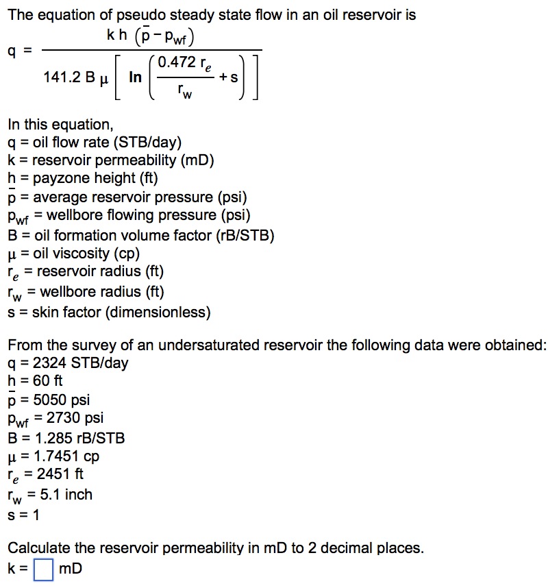
Solved The Equation Of Pseudo Steady State Flow In An Oil Chegg Com
www.chegg.com
Linear Advance Marlin Firmware
marlinfw.org
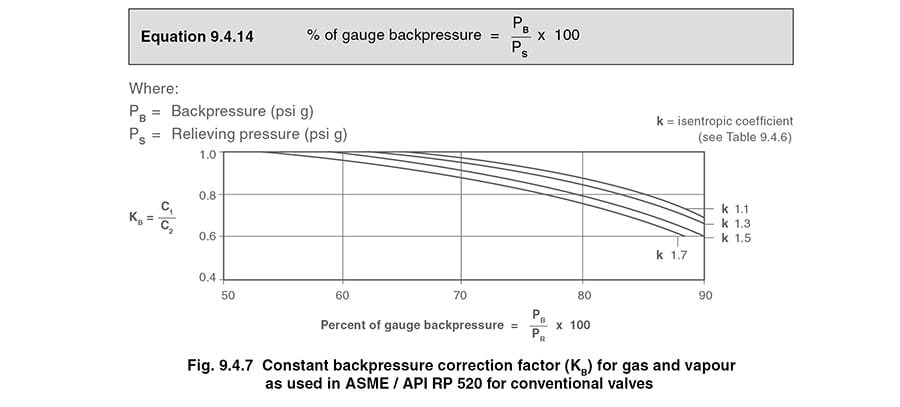
Safety Valve Sizing Spirax Sarco
www.spiraxsarco.com
Https Encrypted Tbn0 Gstatic Com Images Q Tbn 3aand9gcqplg2 C0hko0zgkfu111efi0ehac2js 1tdtjpzjxxx7wlg60e Usqp Cau
encrypted-tbn0.gstatic.com
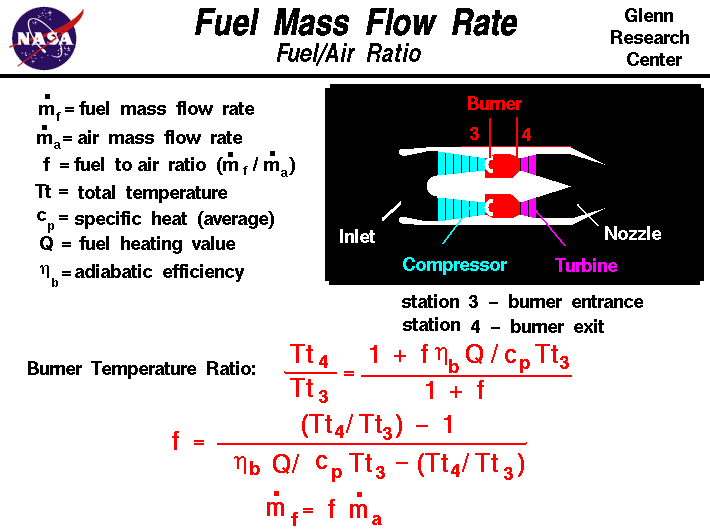
Fuel Mass Flow Rate
www.grc.nasa.gov
Kv Cv Flow Coefficient Valvias
www.valvias.com

Definition Capacity Factor
www.lcresources.com
