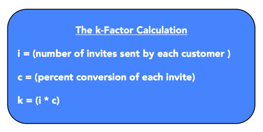
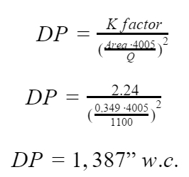
K Factor Calculator Formula

Turbine Flow Meter Calibration Procedure Calibration Instrumentation Forum
instrumentationforum.com

About Resolution Part 1 Shimadzu Shimadzu Corporation
www.shimadzu.com
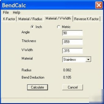
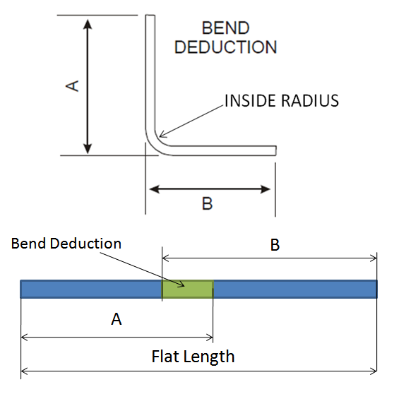
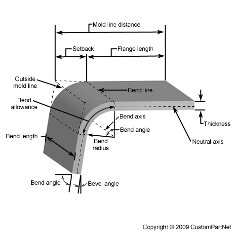
Bendcalc Download Bend Deduction And Bend Allowance Calculator
bendcalc.software.informer.com

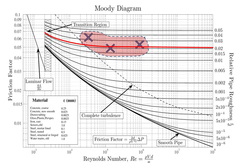
Hydraulics For Fire Protection Ppt Download
slideplayer.com
Summation
help.easypower.com

Free Sprinkler Hydraulic Calculation Software Renewinter
renewinter862.weebly.com
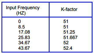
Typically the k factor is going to be between 0 and 5.

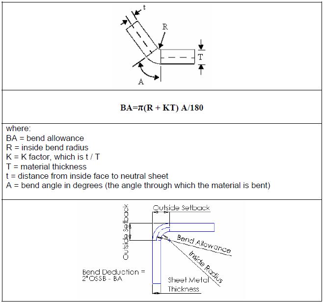
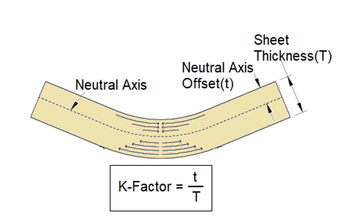
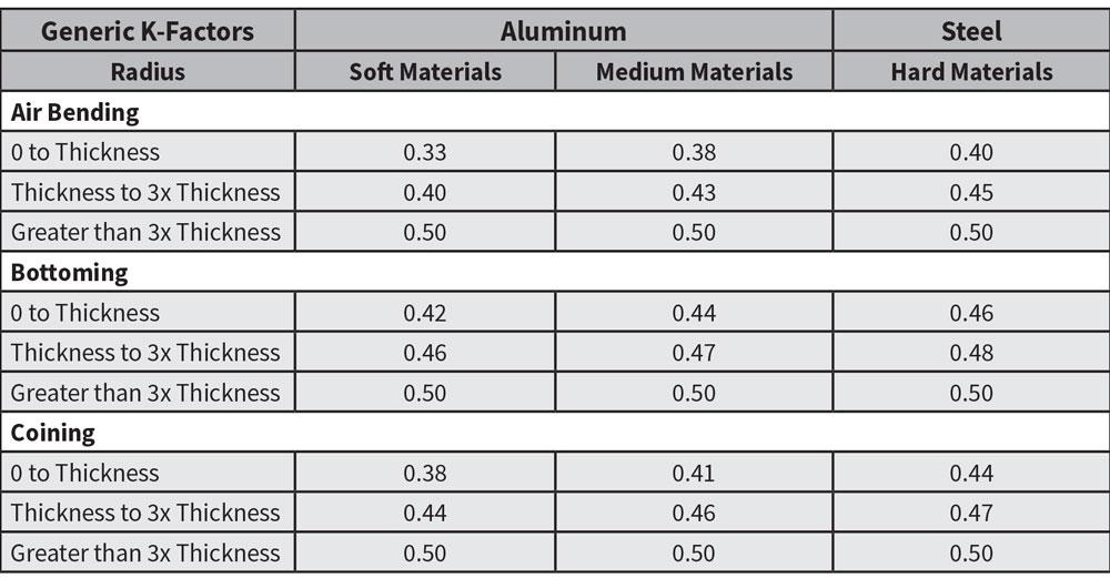
K factor calculator formula. Flow meter k factor. Cad tools use k factor to calculate sheet metal blank size. Die edge radius in.
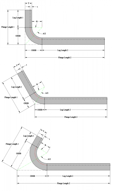
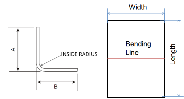
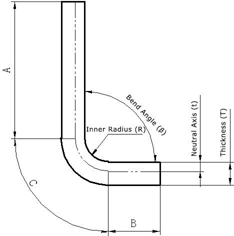
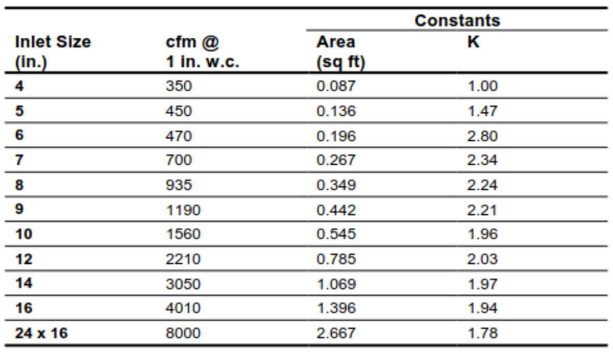
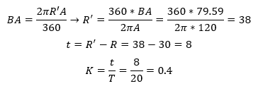
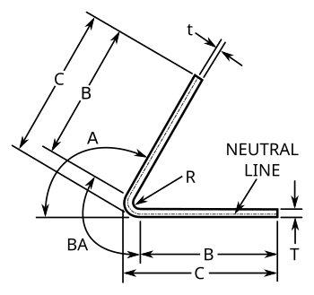
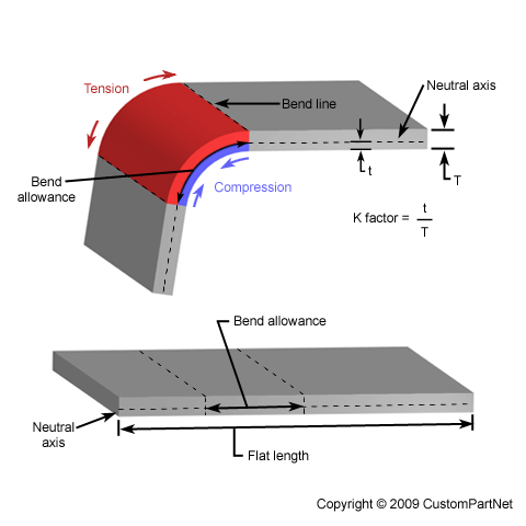
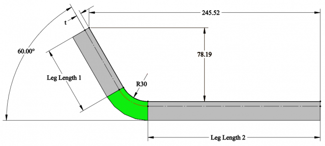
Indeed if we have an 8 inch vav box from the same manufacturer the maximum cfm is 1100 cfm. The k factor is defined as the ratio between the material thickness t and the neutral fibre axis t ie. Since the k factor is based on the property of the metal and its thickness there is no simple way to calculate it ahead of the first bend.
In order to find the k factor you will need to bend a sample piece and deduce the bend allowance. You can use this k factor calculator to calculate k factor using reverse engineering method. Calculate k factor bend allowance and y factor for sheet metal bending.
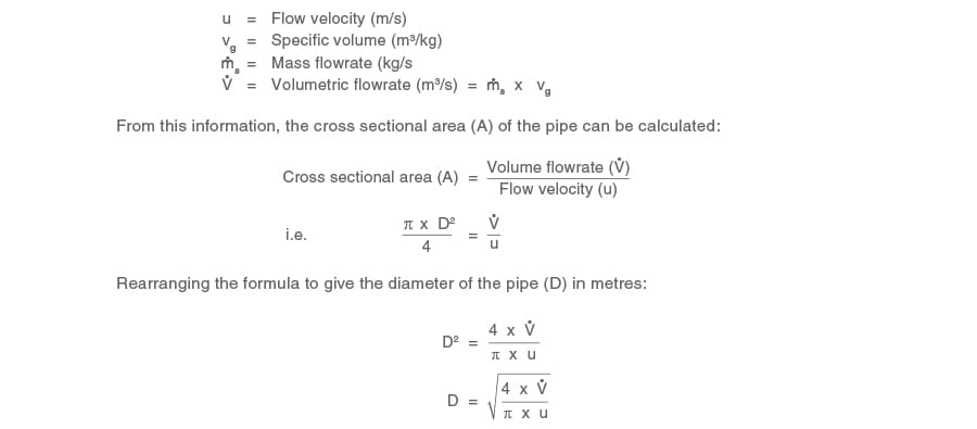
With the formula we can calculate the maximum velocity pressure we will have to measure. The k factor is the most important and elusive variable of bending because it varies both as a function of the material and according to parameters such as angle and tooling. To calculate the neutral axis distance from the inner face t we can subtract inside bend radius from r.
To calculate r which is the radius of the arc on the neutral axis we can use the following equation. The k factor depends on many factors including the material the type of bending operation. We suggest you also read this article on k factor and flat pattern calculations.
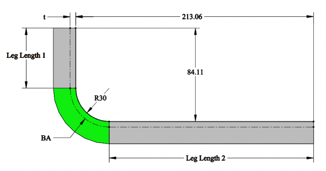
The online free fabrication calculator will help you calculate the k factor y factor bend allowance bend deduction flat size neutral axis arc length etc. The axial design of turbine flow meter is inherently linear within a known turndown range typically 151 based on velocity of the measured fluid. The part of the material that bends.
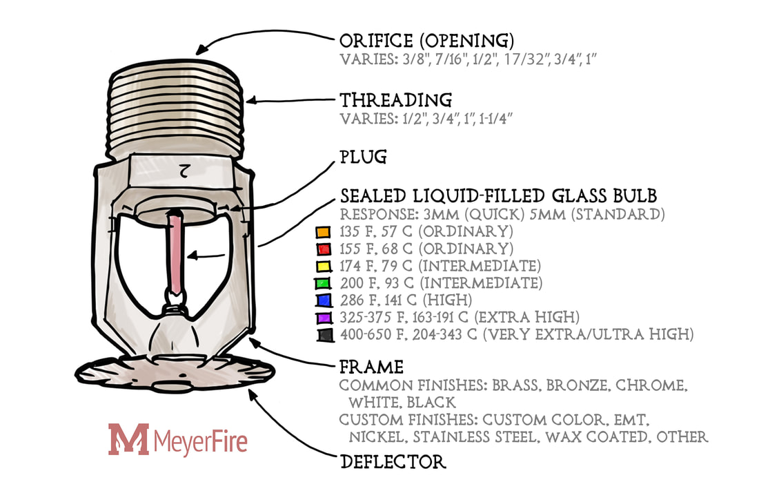
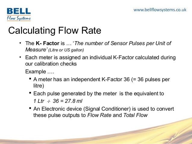
The k factor formula is the start of all hydraulic calculation for fire protection systems for both manual and computerized calculations. The k factor can help you choose the best range transducer for the pressure measurement. Ultimate tensile strength psi.
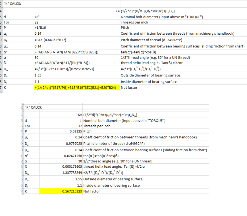
The device has unmatched capability of precise and repeatable k factor generation based on the turning of the balanced rotor and the subsequently generated frequency pulse signal via the magnetic coil assembly providing. The k factor formulation does not take the forming stresses into account but is simply a geometric calculation of the location of the neutral line after the forces are applied and is thus the roll up of all the unknown error factors for a given setup. K factor formula for fire sprinklers 44 0113 328 0350.
A is the bending angle in the above equation so.

Rf K Factor Calculator Rf Stability Factor Calculator
www.rfwireless-world.com

K Factor Docx Fire Sprinkler System Dynamics Mechanics
www.scribd.com
Linear Advance Marlin Firmware
marlinfw.org

Adapting Centrifugation Time Eppendorf Handling Solutions
handling-solutions.eppendorf.com
Fabrication Formulas Sheetmetal Me
sheetmetal.me
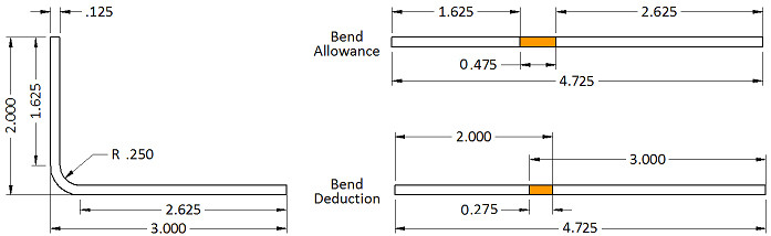
Calculating Bend Allowance Bend Deduction And K Factor
www.javelin-tech.com

K Factors For Vav Airflow Calculation Download Table
www.researchgate.net
K Factor Calculator For Sheet Metal Bending Smlease Design
www.smlease.com

Definition Capacity Factor
www.lcresources.com
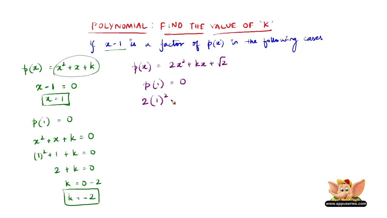
Find The Value Of K If X 1 Is A Factor Of P X In The Given Equations Youtube
www.youtube.com
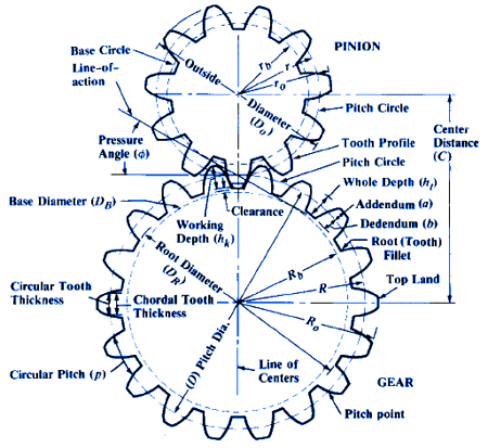
Gear Design Equations And Formula Circular Pitches And Equivalent Diametral Pitches Table Engineers Edge
www.engineersedge.com
Learn To Calculate Yield To Maturity In Ms Excel
www.investopedia.com
Allowance Tables And Formulas
support.ptc.com

Available Options For Wastewater Design Flows Calculation With Cloacas Hidrasoftware
www.hidrasoftware.com
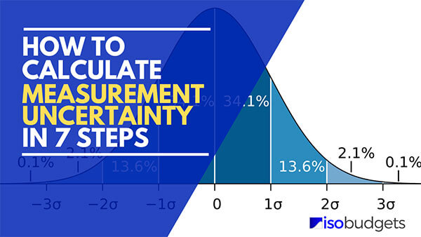
7 Steps To Calculate Measurement Uncertainty Isobudgets
www.isobudgets.com

Calculate K Factor Bend Allowance And Y Factor For Sheet Metal Bending Gasparini Industries
www.gasparini.com
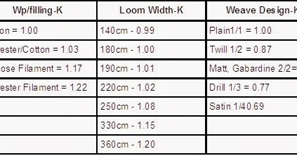
Textile Calculation Different Formula Of Textile Calculation Textile Learner
textilelearner.blogspot.com
Sheet Metal K Factor Bend Allowance And Flat Length Calculations
www.smlease.com

K Factor Calculator Degree Day Systems Inc
www.degreeday.com

Calculate K Factor Bend Allowance And Y Factor For Sheet Metal Bending Gasparini Industries
www.gasparini.com
Pipe Pressure Drop Calculations Formula Theory And Equations
www.pipeflow.com

Minor Losses In Pipe Flow Wikipedia
en.wikipedia.org

Sheet Metal Understanding K Factor
hawkridgesys.com
Sheet Metal Bending Calculation For K Factor Y Factor Bend Allowance Bend Deduction Flat Length
www.machinemfg.com
Compare Flow Of K Factors With New Calculator
www.meyerfire.com
Calculating Bend Allowance Bend Deduction And K Factor
www.javelin-tech.com
Stress Concentration Factor An Overview Sciencedirect Topics
www.sciencedirect.com
The Fine Art Of Sheet Metal Fabrication Manufacturing In China Blog
www.pa-international.com.au

Solidworks Sheet Metal Bending Basics Computer Aided Technology
www.cati.com
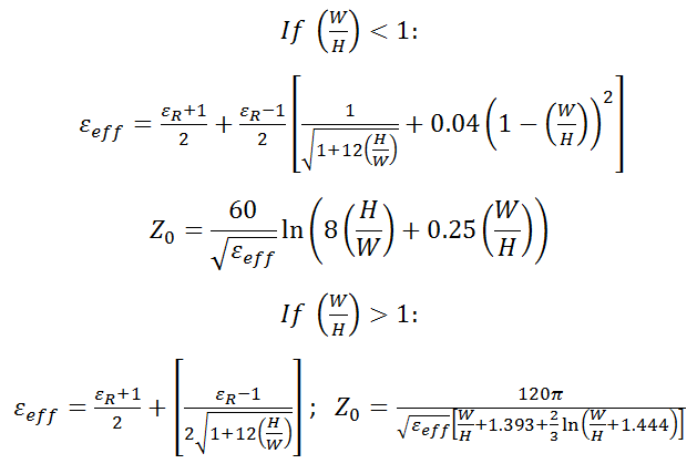
Microstrip Calculator
www.pasternack.com
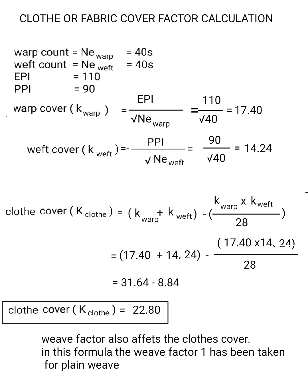
Textile Adviser Clothe Or Fabric Cover Factor Calculation
www.textileadvisor.com

What Is Valve Flow Coefficient Cv Kimray Blog
blog.kimray.com

Measuring Viral Distribution
www.intercom.com
Lec 12 Capacity Analysis Transportation Engineering Dr Lina Shbeeb
www.slideshare.net
Prime Factorization Calculator
www.calculatorsoup.com
Https Encrypted Tbn0 Gstatic Com Images Q Tbn 3aand9gcsiwqlcghpj4cp Mrtny4ounzafwlrd6vjaeues Dirhnv3qle4 Usqp Cau
encrypted-tbn0.gstatic.com

K Factors For Simultaneous Volumetric And Mass Flow Measurement Tutorial Youtube
www.youtube.com
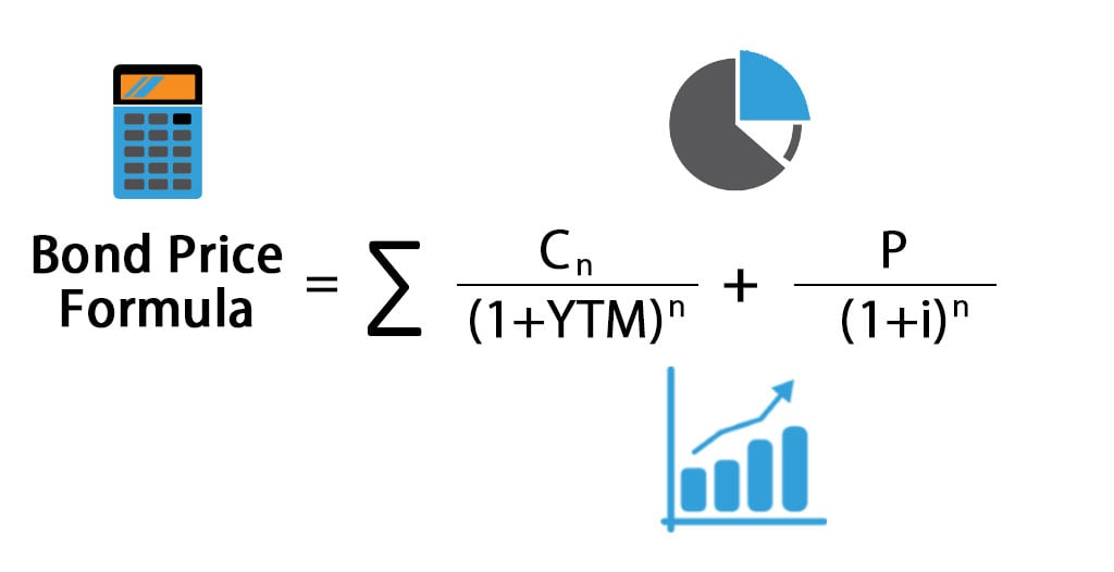
Bond Pricing Formula How To Calculate Bond Price
www.educba.com
Shell Thickness Calculation Formula
p20wforum.info
Sheet Metal Calculator Bend Allowance Equations And Calculator Engineers Edge
www.engineersedge.com
What Is The K Factor And How Do We Use It In Hvac Applications Hvac Brain Northrich Parts
www.hvacbrain.com
Nr505 Concepts In Gis
gisedu.colostate.edu
Calculating Bend Allowance Bend Deduction And K Factor
www.javelin-tech.com
Https Encrypted Tbn0 Gstatic Com Images Q Tbn 3aand9gctf5 Nxksu4pilv5ywyfyl1 Wjg1jit Cavw4ekf14vx5cfm6oo Usqp Cau
encrypted-tbn0.gstatic.com

Plant Load Factor And Its Calculation Electrical Concepts
electricalbaba.com
Bending Metalworking Wikipedia
en.wikipedia.org
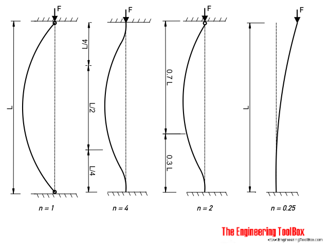
Euler S Column Formula
www.engineeringtoolbox.com
V Notch Weir Discharge Calculator And Equations
www.lmnoeng.com

Calculating The Correct K Factor Value For Your Cad System
designandmotion.net
The K Factor Growth And Going Viral Both Guns Blazing
bothgunsblazingblog.wordpress.com
How To Calculate Power Output Of Wind Windpower Engineering
www.windpowerengineering.com

How To Calculate Bend Allowance For Your Press Brake Industrial Processes Mechanical Engineering
www.scribd.com

Sheet Metal Bend Allowance Calculator
ncalculators.com

Allowance Tables And Formulas
support.ptc.com
Mach And Speed Of Sound Calculator
www.grc.nasa.gov

Arrhenius Equation Calculator Formula Example Calculator Academy
calculator.academy
Pipe Pressure Drop Calculations Formula Theory And Equations
www.pipeflow.com
Macnaught Mx Series Of Oval Gear Flow Meters
www.slideshare.net

The Importance Of Pressure And Temperature Compensation Of Natural Gas Meters
www.2ea.co.uk
Sheet Metal Forming
www.custompartnet.com
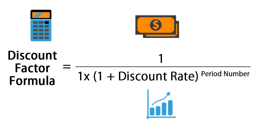
Discount Factor Formula Calculator Excel Template
www.educba.com
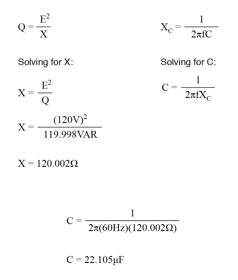
Calculating Power Factor Power Factor Electronics Textbook
www.allaboutcircuits.com

Calculate Bend Radius In Metal Sheet
www.scribd.com
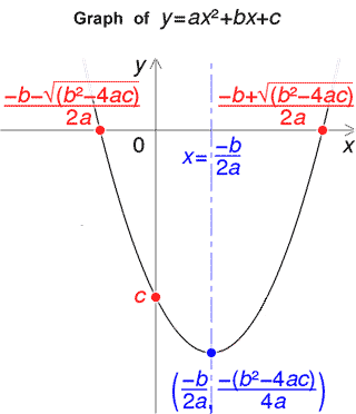
Quadratic Formula Calculator
www.calculator.net
What Is The K Factor And How Do We Use It In Hvac Applications Hvac Brain Northrich Parts
www.hvacbrain.com

Condition Factor Vs Lipid Level Skeena Salmon Energy Monitoring Program
www.skeenasemp.com

Calculate K Factor Bend Allowance And Y Factor For Sheet Metal Bending Gasparini Industries
www.gasparini.com

Adapting Centrifugation Time Eppendorf Handling Solutions
handling-solutions.eppendorf.com
K Factors Y Factors And Press Brake Bending Precision
www.thefabricator.com
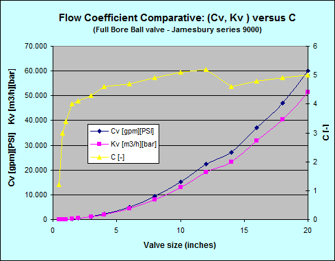
Kv Cv Flow Coefficient Valvias
www.valvias.com
Practical 3 Friction And Minor Losses In Pipes
lo.unisa.edu.au

The Research On The K Factor Of Soil Erodibility In Northeast Black Soil Region Scientific Net
www.scientific.net
Sheet Metal Forming
www.custompartnet.com
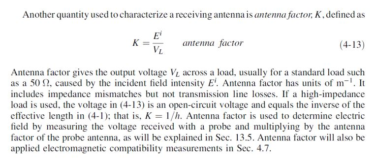
Solved Antenna Factor K Is Defined As Below A Write A Chegg Com
www.chegg.com
Flow Meter K Factor And Calculations Instrumentationtools
instrumentationtools.com
Bend Table Types And Flat Length Calculation
dpt3.dptcorporate.com
Friction Pressure Drop Calculation Campbell Tip Of The Month
www.jmcampbell.com

Rate Constants And The Arrhenius Equation
www.chemguide.co.uk

Solved Sheet Metal Bend Allowence Bend Deduction Experimental Procedure Autodesk Community Inventor
forums.autodesk.com
About Y Factor And K Factor
support.ptc.com
How To Calculate Bend Allowance For Your Press Brake Harsle Machine
www.harsle.com

Sheet Metal Blank Size Calculation Formula In 2020 Sheet Metal Metal Blanks Sheet
in.pinterest.com
Pipes And Pipe Sizing Spirax Sarco
www.spiraxsarco.com

K Factors For Vav Airflow Calculation Download Table
www.researchgate.net
Https Encrypted Tbn0 Gstatic Com Images Q Tbn 3aand9gctevxykk8za Lrw5astoosqw7 Mdvhtam6oawpmq8ugy52o5aot Usqp Cau
encrypted-tbn0.gstatic.com
Calculating Bend Allowance Bend Deduction And K Factor
www.javelin-tech.com
2
What Is Wrong With My Nut K Factor Calculation Welding Bonding Fastener Engineering Eng Tips
www.eng-tips.com

Clear Plastic Tubing Sprinkler K Factor Calculator
clearplastictubing.blogspot.com
Editing K Factor
www.nirvanatec.com

Determining The Blank Length Of Bent Metal Components
www.swiftmetal.com.au
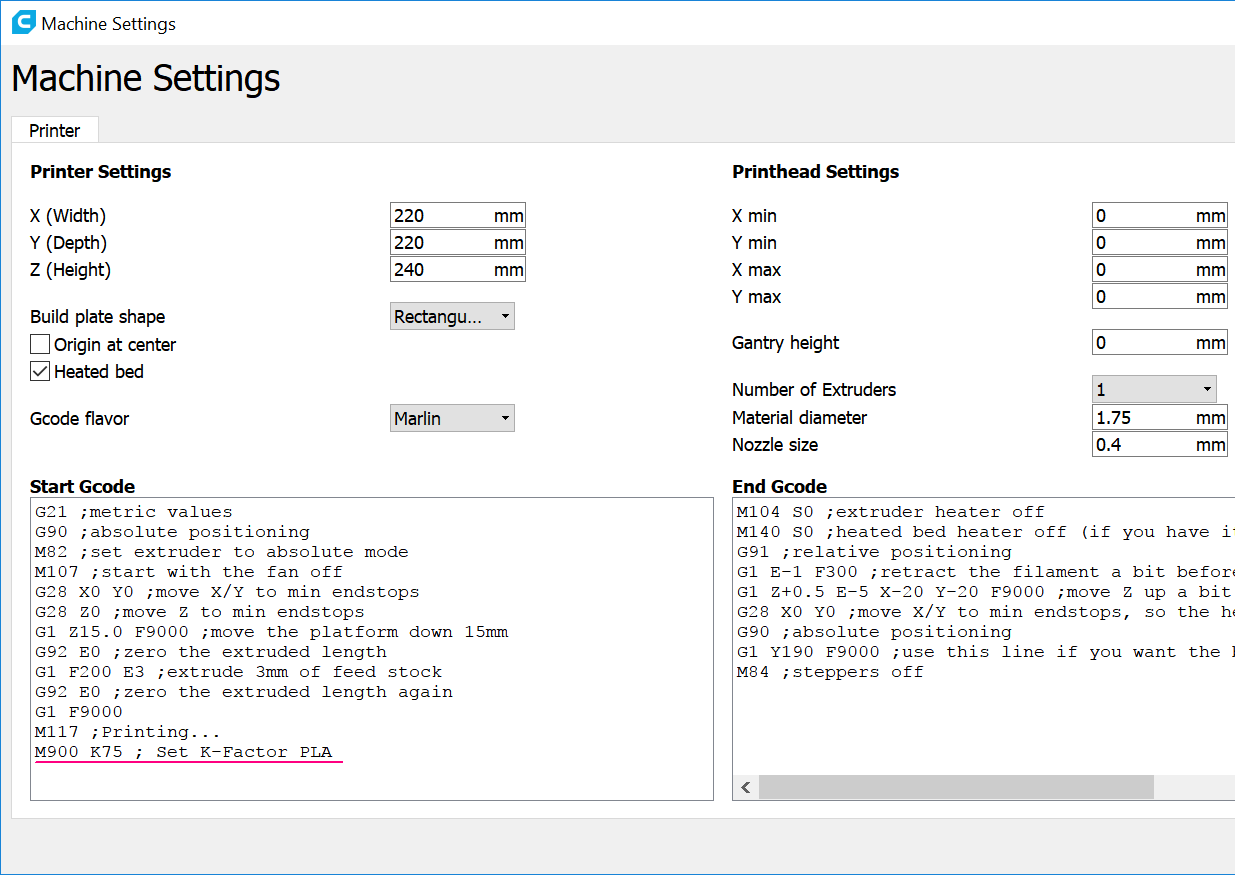
Linear Advance Marlin Firmware
marlinfw.org

Line Speed Calculation Formula
line-speed-calculation-formula.piarcoremezcla.space
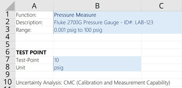
7 Steps To Calculate Measurement Uncertainty Isobudgets
www.isobudgets.com
Https Encrypted Tbn0 Gstatic Com Images Q Tbn 3aand9gctsu97qhcwhbu4e9 Z S1yug7kgpvdjovn Nvqqmp0pftormcwc Usqp Cau
encrypted-tbn0.gstatic.com

Sample Problem Equivalent Length Calculation For Piping Fittings Enggcyclopedia
www.enggcyclopedia.com
Rate Constants And The Arrhenius Equation
www.chemguide.co.uk
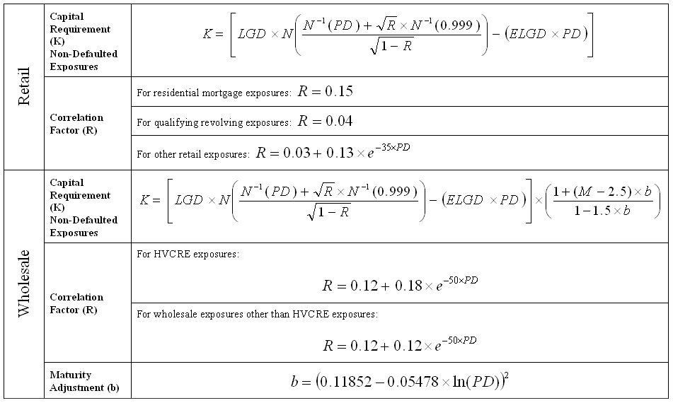
Basel Ii Capital Accord Notice Of Proposed Rulemaking Npr Preamble Calculation Of Risk Weighted Assets
www.federalreserve.gov
